Sunday, February 25, 2018

Magnetism & Electromagnetism

Magnetism

Bar magnet
One of the fundamental properties of matter is magnetism. Magnetism is related to electricity. In fact, the fundamental cause of all magnetism effects is due to the movements of electric charges. Common materials for magnets are iron, steel, cobalt and nickel. They are suitable to make magnets due to their atomic structures.
  • An atom consists of a central, positively charged nucleus surrounded by negatively charged electrons. A common view of the electrons is that they orbit around the central nucleus, while spinning on their axes. This view is not exactly correct, but its alright at this level. Due to the charge on the electrons, the movements of these electrons will give rise to magnetic effects. These magnetic effects can be seen as tiny atomic magnets.
  • The tiny magnetic effects occurs in all substances. Then, why aren’t all substances magnetic? This is due to their atomic structures. In those materials, the electrons are arranged in configurations that result in the magnetic effects cancelling out one another.
  • Once those tiny atomic magnets are aligned properly, it will give rise to a strong combined magnetic effect. At this point, the substance is considered to be magnetised and is a proper magnet.
  • Lodestone is the only natural substance that behaves as a magnet. Magnetic materials like steel and iron can be made into magnets.

Properties of magnets

Since  magnetism is related to the movements of electrons. It is not surprising that the basic ideas of magnetism is very similar to those of electrostatics.
  • All the magnets have two types of poles: north-seeking poles or north poles and south-seeking poles or south poles.
  • The magnetic strength is the strongest at the poles of the magnet.
  • When you freely suspend a bar magnet in a horizontal position, the magnetic field of the bar magnet will interact with the magnetic field of the Earth. This will cause the bar magnet to come to rest in a north-south direction, where the north pole of the magnet points to the north pole of the Earth.
  • Like poles repel and unlike poles attract. (just as like charges repel and unlike charges attract).
  • Magnets attract magnetic materials such as iron, steel, cobalt and nickel.
  • The stronger a magnet, the larger will be the attractive or repulsive force between other magnets.
  • The closer together the two magnets are, the greater is the magnetic force between them.

Note:
  • All magnets have a north and south poles – 2 poles. Cutting a bar magnet in half simply produces two smaller magnets, each with its own north and south poles. What if you cut the half-bar-magnet? You will just obtain two smaller magnets, each with its own north and south poles. There is currently no experimental nor theoretical evidence for the existence of a magnet containing only 1 pole (magnetic monopole). If a magnetic monopole is found, most of the Physics texts will have to be rewritten.
  • Only magnets can be made to repel each other. Otherwise, the magnets will attract all other magnetic materials.
  • The Earth has a giant magnet, its axis is oriented more or less in the direction of the Earth’s rotation. The North pole of the Earth is actually the south pole of the Earth’s magnet. (The magnetic poles actually does not align perfectly with the real north and south pole. There is a small deviation. But let’s not concern ourselves with this for now.)

Magnetic materials are matter that is attracted by magnets.
  • Magnetic materials can be made into magnets.

e.g. Iron, steel, nickel, cobalt and many alloys based on these metals.

Non-magnetic materials are matter that is not attracted by magnets.
  • Non-magnetic materials cannot be made into magnets.

e.g. Wood, glass, plastics and metals such as copper and brass.

Note: It would be good if you can remember the examples.

induced Magnetism & Electrical Method Of Magnetisation

Magnetic Induction is one of the ways making magnetic materials like steel and iron into magnets. In other words, magnetic induction is a process of inducing magnetism in an ordinary piece of magnetic material.
  • This method involves simply placing the magnetic material (soft iron) close to a strong magnet without touching.
  • The soft iron bar becomes an induced magnet with the end nearer the magnet having opposite polarity to that of the magnet.
  • Hence, the soft iron bar is attracted and attached to the permanent magnet. Magnetic induction process reveals how magnetic materials can be attracted to magnets.
  • Induced magnetism is a temporary process. If the permanent magnet is removed, the magnetic material will usually lose its induced magnetism.

Electrical method for magnetisation

For magnetization, a direct current flowing into a solenoid (a long insulated wire coiled into a cylinder) produces a magnetic field that, inside the coil, is uniform in strength and direction.
  • The solenoid becomes a magnet.

A steel bar placed inside the coil for a short while becomes magnetised due to magnetic induction from the solenoid.
  • The polarities of the magnet depend on the direction of current flow.

Magnetisation by electric current method creates more powerful magnets than other magnetization methods such as stroking.

Magnetic Field And Magnetic Field Lines

Magnetic Field is the region around a magnet where other magnetic material will experience a force.
A magnetic field can be graphically represented by magnetic field lines which indicates its strength and direction.
Note: Magnetic field is a vector quantity! (It has both magnitude AND direction!)
  • When the field lines are close together at a point, the point is said to have a strong magnetic field.
  • Arrows in the field lines outside the magnets show the direction in which a free north pole would move (from north pole to south pole).
  • Field lines NEVER cross over.
  • Compass is used to find the direction and pattern of magnetic field. It has a permanent magnet needle which is free to rotate in a horizontal plane. The north pole of compass magnet (arrow head) will align and point along the magnetic field line direction.
IMPORTANT: Please note that for the last two diagrams, the field lines are NOT pushing against one another. Do NOT be tempted to say that the like poles repel because the field lines push against one another. It is NOT correct!

Interesting tidbits:
Magnetic field strength can be measured using a teslameter.

Plotting of magnetic field lines with a compass

Apparatus Needed: Bar magnet, plotting paper and plotting compass.

Procedure:
  1. Place the bar magnet at the centre of the piece of paper so that its north pole is aligned as shown.
  2. Place the compass near one pole of the magnet, and mark the positions of the ends N and S, of the compass needle by pencil dots. Then, move the compass until  the end of the compass is over the second dot, and mark the new position of the other with a third dot.
  3. Repeat the above until reaching the other pole. Join the series of dots and this will give a field line of the magnetic field. Use this method to plot other field lines on both sides of this magnet.

temporary and permanent magnets

Iron as a temporary magnet:
  • Iron can be easily magnetised or demagnetised (soft magnetic material. It can even be magnetized by a weak magnetic field. it is therefore suitable to be used in temporary magnets.
  • When mixed with other metals (e.g. Ni, Cu, Mn, Si), powerful temporary magnets can be made.
  • These temporary magnets are used to make temporary electromagnets. Electromagnets lose its magnetism when it is removed from magnetising fields. Electromagnets are very useful because they can be turned on and off and their strengths can be varied.
  • In order to shield or contain any magnetic effects, soft permeable iron is also used as effective magnetic shields. (magnetic keepers)

E.g. Electromagnets can be used for such tasks as moving cars or sorting metals from other landfill materials. Other applications are in circuit breakers, magnetic relays, electric bells, audio and video tapes transformers etc.

Steel as a permanent magnet
  • Compared to iron, steel cannot be easily magnetised or demagnetised (hard magnetic material). It can only be magnetized by a strong magnetic field. But, steel has the ability to retain its magnetism once it is magnetized. This trait allows steel to be suitable to be used in permanent magnets.
  • Steel is typically mixed with other magnetic material to ensure structural stability. In this way, strong permanent magnets are made.

E.g. Permanent magnets are used in compasses, magnetic door catches, moving coil galvanometers, d.c. motors, a.c. generators, loudspeakers, and for many other purposes.

Note: Theoretical limit for a permanent magnetic field is 5 Tesla. Electromagnets made with ordinary wires can produce steady fields of 34 Tesla.

Magnetic field due to current in a straight wire

Movement of electric charge is an underlying cause of magnetism. Hence, an electric current, being a flow of charge, produces a magnetic field. If the current is flowing in a wire, the shape of the magnetic field is dependent on the configuration of the wire.
The magnetic field lines produced by a current in a straight wire are in the form of circles with the wire as its centre.

magnetic field wire

Right-hand rule can be used to find the direction of the magnetic field produced due to current flow.
  • Right-hand rule: Grasp the wire with right hand so that the thumb points in the direction of the conventional current, then the wrapped fingers will encircle the wire in the direction of the magnetic field.

The magnetic field is strong in the region around the wire and weakens with increasing distance, i.e., the field lines near the wire are drawn closer to another. With increasing distances, concentric circles are further apart.

The larger the current, the stronger is the magnetic field.

Magnetic field due to current in a solenoid

 
solenoid magnetic field
Solenoid consists of a length of insulated wire coiled into a cylinder shape.
  • Current in solenoid produces a stronger magnetic field inside the solenoid than outside. The field lines in this region are parallel and closely spaced showing the field is highly uniform in strength and direction.
  • Field lines outside the solenoid are similar to that of a bar magnet, and it behaves in a similar way – as if it had a north pole at one end and south pole at the other end. Strength of the field diminishes with distance from the solenoid.
  • Strength of the magnetic field can be increased by:
    1. increasing the current in the coil
    2. increasing the number of coils in the solenoid; and
    3. using a soft iron core within the solenoid.
  • Reversing the direction of the current reverses the direction of the magnetic field.

Right-hand rule can be used to find the direction of the magnetic field. In this case, point the wrapped fingers (along the coil) in the direction of the conventional current. Then, the thumb will point to the direction of magnetic field within the solenoid.

Electric bell

The well-known application of electromagnet is the electric bell.
  • When the ‘push’ switch is depressed, the circuit is closed. Current passes through the electromagnet windings and the core becomes magnetised.
  • The magnetised core attracts the iron armature which makes the striker hits the gong.
  • However, the movement of the armature opens the ‘make and break’ switch which switches the electromagnet off. The iron armature springs back to its original position, closing the ‘make and break’ switch and start the cycle again.

Notes:
  • Soft iron is used to make electromagnets as it gains and loses magnetism quickly depending on existence of magnetic fields. The armature is also made of soft iron which can induce magnetism rapidly.
  • No matter what direction is the current flow, the bell rings continuously as long as the ‘push’ switch is closed because any pole induces the armature.

Circuit breaker

An excess current circuit breaker is a ‘trip’ switch opened by an electromagnet in the same circuit when the current through the windings exceeds a certain value.
Unlike a ‘make and break’ switch, a ‘trip’ is designed to stay open after it has been opened by the electromagnet. The trip switch is reset manually after the cause of the excessive current has been removed.

Force on current-carrying conductor

When current-carrying conductor is placed in a magnetic field, it will experience a force when the magnetic field direction is not parallel to the current direction. The magnitude of the force is maximum when the magnetic field and current directions are mutually perpendicular to each other. The force decreases when the angle between the magnetic field and current directions is smaller than 
90∘.
Factors that affect the strength of the force:
  • Angle between the magnetic field and current directions (More about this below)
  • Magnetic field strength (Stronger magnetic field → stronger force)
  • Amount of current in conductor (Higher current → stronger force)
  • Length of conductor within magnetic field (Longer conductor → stronger force)
If the current direction is PARALLEL to the magnetic field, there will NO force on the conductor by the magnetic field. The magnitude of the force is MAXIMUM when the angle between the magnetic field and current direction is 90∘.
This is commonly exploited to produce a turning effect in a current-carrying coil to produce an electric motor.
It does not have to be a current carrying conductor to experience a force due to the magnetic field. The magnetic field actually interacts with the moving electrons in the conductor to produce the force. Hence, electrons that are moving in the direction perpendicular to the magnetic field will experience the force as well. This means that if you pass an electron beam through a magnetic field, it will be deflected. (provided it is perpendicular)

How to Study Physics: 5 Techniques to Improve your Memory

1. Master the Basics:

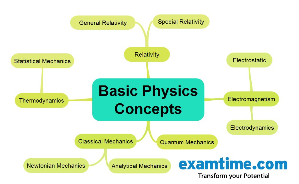
Physics is based on a number of central theories from which everything else develops. It is therefore very likely that the problems you will have to solve in the exam will be based on these core concepts or a variation of these. Consequently, instead of trying to memorize complex problems, it is advisable to assimilate the basic concepts and theories which will help you understand the underlying principles and the connection between different subjects.
An effective way to get an overview of these basic physical concepts and their relationships is by creating a Mind Map such as below:
How to Study Physics Mind Map

2. Strengthen Your Maths Skills:

As already mentioned, if you are studying Physics then you will see that it incorporates many mathematical elements. This means that you would easily master this subject if you were adept at tackling multiple formulas and problems. Review or study Mathematics alongside your Physics and this will help you to improve your management of the formulas and concepts.
 
3. Simplify:
Try to simplify the situation as much as possible. The Physics problem you are reading may seem difficult to solve at first but take another look and begin to analyze it and you will realize that is easier than you first thought. It is important to remain calm and try to bring the problem to a situation which you are familiar with by simplifying it in your mind.

4. Use Drawings:

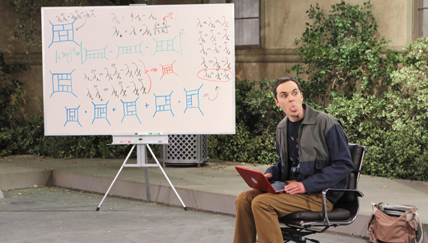
A great way to implement the point above is through drawings or graphics. We have already discussed the benefits of Mind Maps but drawings can also be essential when in order to understand and study physics. Whenever you can, we recommend that you perform a drawing to illustrate a concept just like Sheldon below:
how to study physics - Big Bang Theory

5. Use Flashcards to Study:

Take note of new words, units of measure, general principles and other concepts that arise. This will help you follow the thread of theory and strengthen the new information which will have positive consequences when faced with problem solving.

Monday, July 28, 2014

AC Waveform and AC Circuit Theory

The AC Waveform

Direct Current or D.C. as it is more commonly called, is a form of current or voltage that flows around an electrical circuit in one direction only, making it a “Uni-directional” supply. Generally, both DC currents and voltages are produced by power supplies, batteries, dynamos and solar cells to name a few. A DC voltage or current has a fixed magnitude (amplitude) and a definite direction associated with it. For example, +12V represents 12 volts in the positive direction, or -5V represents 5 volts in the negative direction.
We also know that DC power supplies do not change their value with regards to time, they are a constant value flowing in a continuous steady state direction. In other words, DC maintains the same value for all times and a constant uni-directional DC supply never changes or becomes negative unless its connections are physically reversed. An example of a simple DC or direct current circuit is shown below.

DC Circuit and Waveform

DC circuit and waveform
An alternating function or AC Waveform on the other hand is defined as one that varies in both magnitude and direction in more or less an even manner with respect to time making it a “Bi-directional” waveform. An AC function can represent either a power source or a signal source with the shape of an AC waveform generally following that of a mathematical sinusoid as defined by:-A(t) = Amax x sin(2πƒt).
The term AC or to give it its full description of Alternating Current, generally refers to a time-varying waveform with the most common of all being called a Sinusoid better known as a Sinusoidal Waveform. Sinusoidal waveforms are more generally called by their short description as Sine Waves. Sine waves are by far one of the most important types of AC waveform used in electrical engineering.
The shape obtained by plotting the instantaneous ordinate values of either voltage or current against time is called an AC Waveform. An AC waveform is constantly changing its polarity every half cycle alternating between a positive maximum value and a negative maximum value respectively with regards to time with a common example of this being the domestic mains voltage supply we use in our homes.
This means then that the AC Waveform is a “time-dependent signal” with the most common type of time-dependant signal being that of the Periodic Waveform. The periodic or AC waveform is the resulting product of a rotating electrical generator. Generally, the shape of any periodic waveform can be generated using a fundamental frequency and superimposing it with harmonic signals of varying frequencies and amplitudes but that’s for another tutorial.
Alternating voltages and currents can not be stored in batteries or cells like direct current can, it is much easier and cheaper to generate them using alternators and waveform generators when needed. The type and shape of an AC waveform depends upon the generator or device producing them, but all AC waveforms consist of a zero voltage line that divides the waveform into two symmetrical halves. The main characteristics of an AC Waveform are defined as:

AC Waveform Characteristics

  • • The Period, (T) is the length of time in seconds that the waveform takes to repeat itself from start to finish. This can also be called the Periodic Time of the waveform for sine waves, or thePulse Width for square waves.
  • • The Frequency, (ƒ) is the number of times the waveform repeats itself within a one second time period. Frequency is the reciprocal of the time period, ( ƒ = 1/T ) with the unit of frequency being the Hertz, (Hz).
  • • The Amplitude (A) is the magnitude or intensity of the signal waveform measured in volts or amps.
In our tutorial about Waveforms ,we looked at different types of waveforms and said that “Waveforms are basically a visual representation of the variation of a voltage or current plotted to a base of time”. Generally, for AC waveforms this horizontal base line represents a zero condition of either voltage or current. Any part of an AC type waveform which lies above the horizontal zero axis represents a voltage or current flowing in one direction.
Likewise, any part of the waveform which lies below the horizontal zero axis represents a voltage or current flowing in the opposite direction to the first. Generally for sinusoidal AC waveforms the shape of the waveform above the zero axis is the same as the shape below it. However, for most non-power AC signals including audio waveforms this is not always the case.
The most common periodic signal waveforms that are used in Electrical and Electronic Engineering are the Sinusoidal Waveforms. However, an alternating AC waveform may not always take the shape of a smooth shape based around the trigonometric sine or cosine function. AC waveforms can also take the shape of either Complex Waves, Square Waves or Triangular Waves and these are shown below.

Types of Periodic Waveform

periodic AC waveform
The time taken for an AC Waveform to complete one full pattern from its positive half to its negative half and back to its zero baseline again is called a Cycle and one complete cycle contains both a positive half-cycle and a negative half-cycle. The time taken by the waveform to complete one full cycle is called the Periodic Time of the waveform, and is given the symbol “T”.
The number of complete cycles that are produced within one second (cycles/second) is called theFrequency, symbol ƒ of the alternating waveform. Frequency is measured in Hertz, ( Hz ) named after the German physicist Heinrich Hertz.
Then we can see that a relationship exists between cycles (oscillations), periodic time and frequency (cycles per second), so if there are ƒ number of cycles in one second, each individual cycle must take1/ƒ seconds to complete.

Relationship Between Frequency and Periodic Time

frequency and periodic time relationship

AC Waveform Example No1

1. What will be the periodic time of a 50Hz waveform and 2. what is the frequency of an AC waveform that has a periodic time of 10mS.
1).
periodic time
2).
frequency
Frequency used to be expressed in “cycles per second” abbreviated to “cps”, but today it is more commonly specified in units called “Hertz”. For a domestic mains supply the frequency will be either 50Hz or 60Hz depending upon the country and is fixed by the speed of rotation of the generator. But one hertz is a very small unit so prefixes are used that denote the order of magnitude of the waveform at higher frequencies such as kHz, MHz and even GHz.

Definition of Frequency Prefixes

PrefixDefinitionWritten asPeriodic Time
KiloThousandkHz1mS
MegaMillionMHz1uS
GigaBillionGHz1nS
TerraTrillionTHz1pS

Amplitude of an AC Waveform

As well as knowing either the periodic time or the frequency of the alternating quantity, another important parameter of the AC waveform is Amplitude, better known as its Maximum or Peak value represented by the terms, Vmax for voltage or Imax for current. The peak value is the greatest value of either voltage or current that the waveform reaches during each half cycle measured from the zero baseline. Unlike a DC voltage or current which has a steady state that can be measured or calculated using Ohm’s Law, an alternating quantity is constantly changing its value over time.
For pure sinusoidal waveforms this peak value will always be the same for both half cycles ( +Vm = -Vm ) but for non-sinusoidal or complex waveforms the maximum peak value can be very different for each half cycle. Sometimes, alternating waveforms are given a peak-to-peak, Vp-p value and this is simply the distance or the sum in voltage between the maximum peak value, +Vmax and the minimum peak value, -Vmax during one complete cycle.

The Average Value of an AC Waveform

The average or mean value of a continuous DC voltage will always be equal to its maximum peak value as a DC voltage is constant. This average value will only change if the duty cycle of the DC voltage changes. In a pure sine wave if the average value is calculated over the full cycle, the average value would be equal to zero as the positive and negative halves will cancel each other out. So the average or mean value of an AC waveform is calculated or measured over a half cycle only and this is shown below.

Average Value of a Non-sinusoidal Waveform

AC waveform average value
To find the average value of the waveform we need to calculate the area underneath the waveform using the mid-ordinate rule, trapezoidal rule or the Simpson’s rule found commonly in mathematics. The approximate area under any irregular waveform can easily be found by simply using the mid-ordinate rule.
The zero axis base line is divided up into any number of equal parts and in our simple example above this value was nine, ( V1 to V9 ). The more ordinate lines that are drawn the more accurate will be the final average or mean value. The average value will be the addition of all the instantaneous values added together and then divided by the total number. This is given as.

Average Value of an AC Waveform

coordinate rule
Where: n equals the actual number of mid-ordinates used.
For a pure sinusoidal waveform this average or mean value will always be equal to 0.637 x Vmax and this relationship also holds true for average values of current.

The RMS Value of an AC Waveform

The average value of an AC waveform is NOT the same value as that for a DC waveforms average value. This is because the AC waveform is constantly changing with time and the heating effect given by the formula ( P = I 2.R ), will also be changing producing a positive power consumption. The equivalent average value for an alternating current system that provides the same power to the load as a DC equivalent circuit is called the “effective value”.
This effective power in an alternating current system is therefore equal to: ( I 2.R.Average ). As power is proportional to current squared, the effective current, I will be equal to √ I squared Ave. Therefore, the effective current in an AC system is called the Root Mean Squared or R.M.S. value and RMS values are the DC equivalent values that provide the same power to the load.
The effective or RMS value of an alternating current is measured in terms of the direct current value that produces the same heating effect in the same value resistance. The RMS value for any AC waveform can be found from the following modified average value formula.

RMS Value of an AC Waveform

AC waveform rms
Where: n equals the number of mid-ordinates.
Electrical Circuit Theory and Technology
List Price: Click to see...
Current Price: Click to see...
Buy Now
Price Disclaimer
For a pure sinusoidal waveform this effective or R.M.S. value will always be equal to 1/√2 x Vmax which is equal to 0.707 x Vmax and this relationship holds true for RMS values of current. The RMS value for a sinusoidal waveform is always greater than the average value except for a rectangular waveform. In this case the heating effect remains constant so the average and the RMS values will be the same.
One final comment about R.M.S. values. Most multimeters, either digital or analogue unless otherwise stated only measure the R.M.S. values of voltage and current and not the average. Therefore when using a multimeter on a direct current system the reading will be equal to I = V/R and for an alternating current system the reading will be equal to Irms = Vrms/R.
Also, except for average power calculations, when calculating RMS or peak voltages, only use VRMS to find IRMS values, or peak voltage, Vp to find peak current, Ip values. Do not mix the two together average, RMS or peak values as they are completely different and your results will be incorrect.

Form Factor and Crest Factor

Although little used these days, both Form Factor and Crest Factor can be used to give information about the actual shape of the AC waveform. Form Factor is the ratio between the average value and the RMS value and is given as.
AC waveform form factor
For a pure sinusoidal waveform the Form Factor will always be equal to 1.11.
Crest Factor is the ratio between the R.M.S. value and the Peak value of the waveform and is given as.
AC waveform crest factor
For a pure sinusoidal waveform the Crest Factor will always be equal to 1.414.

AC Waveform Example No2

A sinusoidal alternating current of 6 amps is flowing through a resistance of 40Ω. Calculate the average voltage and the peak voltage of the supply.
The R.M.S. Voltage value is calculated as:
rms voltage
The Average Voltage value is calculated as:
average voltage
The Peak Voltage value is calculated as:
peak voltage